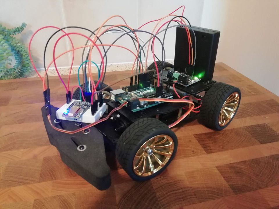
Smartphone Controlled Arduino Car via Bluetooth
This is an older post from when this site covered general embedded learning. The site now focuses on modernising classic vehicles.
Required Components
- A chassis
- Arduino Uno
- Maker Drive driver
- Adafruit Bluefruit LE UART Friend
- Smartphone - Android or iPhone
- Batteries - Example: 4 x AA (1.5V)
- Servo Motor
- DC Motor - You might need a second motor depending on your chassis
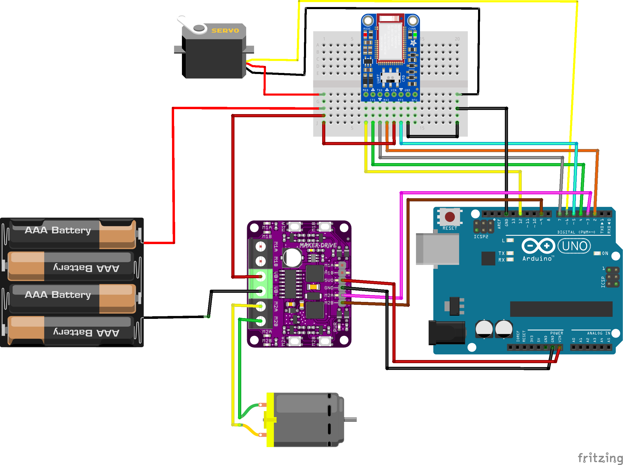
Circuit Diagram
Code
The software is based on the Adafruit Bluefruit and Cytron Motor Driver libraries.
You can check out the code on GitHub.
Notes
Chassis
You could use most chassis with this tutorial. However, you might need to make changes to the code where relevant. For example, if you only have two wheels, you need to change the servo code to make the motors turn the robot.
Multiple power sources needed?
Initially, I thought I needed to have multiple power sources to run everything simultaneously. So I used a 9V battery to power some of the peripherals in the first version of this car. But, in my research, I found out that the 9V battery is quite inefficient.
After reading the manuals for all the items used and calculating that the 4 x AA batteries should be able to power them all, I managed to get that to work with a little redesign.
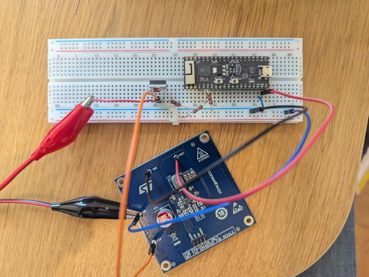
Setting up Bluefruit LE UART Friend
These steps are based on the official documentation, and I recommend going through those as well.
- Download the app
Start by downloading the Bluefruit iOS App or Android App. Easily and quickly done.
- Solder the pins - IMPORTANT!
The module comes with pins to make it easier to connect with a breadboard. I highly recommend soldering those pins to the module. The connection can be flaky otherwise and cause the module to be unreliable.
- Wiring
I suggest starting with the default pinout in the documentation. That's to make sure it works as intended. Then later, when adding peripherals to the project, test out other pins if needed.
- Software Configurations
The code I used is built on the supplied Adafruit code. There are a few code changes that are needed for this project.
First, make sure to uncomment this part in the controller.ino file:
// Create the bluefruit object, either software serial...uncomment these lines
SoftwareSerial bluefruitSS = SoftwareSerial(BLUEFRUIT_SWUART_TXD_PIN, BLUEFRUIT_SWUART_RXD_PIN);

Adafruit_BluefruitLE_UART ble(bluefruitSS, BLUEFRUIT_UART_MODE_PIN,
                      BLUEFRUIT_UART_CTS_PIN, BLUEFRUIT_UART_RTS_PIN);
To match the wiring setup, you must adjust the PIN variables in BluefruitConfig.h.
Default setup:
// SOFTWARE UART SETTINGS
#define BLUEFRUIT_SWUART_RXD_PIN       9    // Required for software serial!
#define BLUEFRUIT_SWUART_TXD_PIN       10   // Required for software serial!
#define BLUEFRUIT_UART_CTS_PIN         11   // Required for software serial!
#define BLUEFRUIT_UART_RTS_PIN         8   // Optional, set to -1 if unused
Final setup for the project:
// SOFTWARE UART SETTINGS
#define BLUEFRUIT_SWUART_RXD_PIN       2   // Required for software serial!
#define BLUEFRUIT_SWUART_TXD_PIN       7   // Required for software serial!
#define BLUEFRUIT_UART_CTS_PIN         4   // Required for software serial!
#define BLUEFRUIT_UART_RTS_PIN         5   // Optional, set to -1 if unused
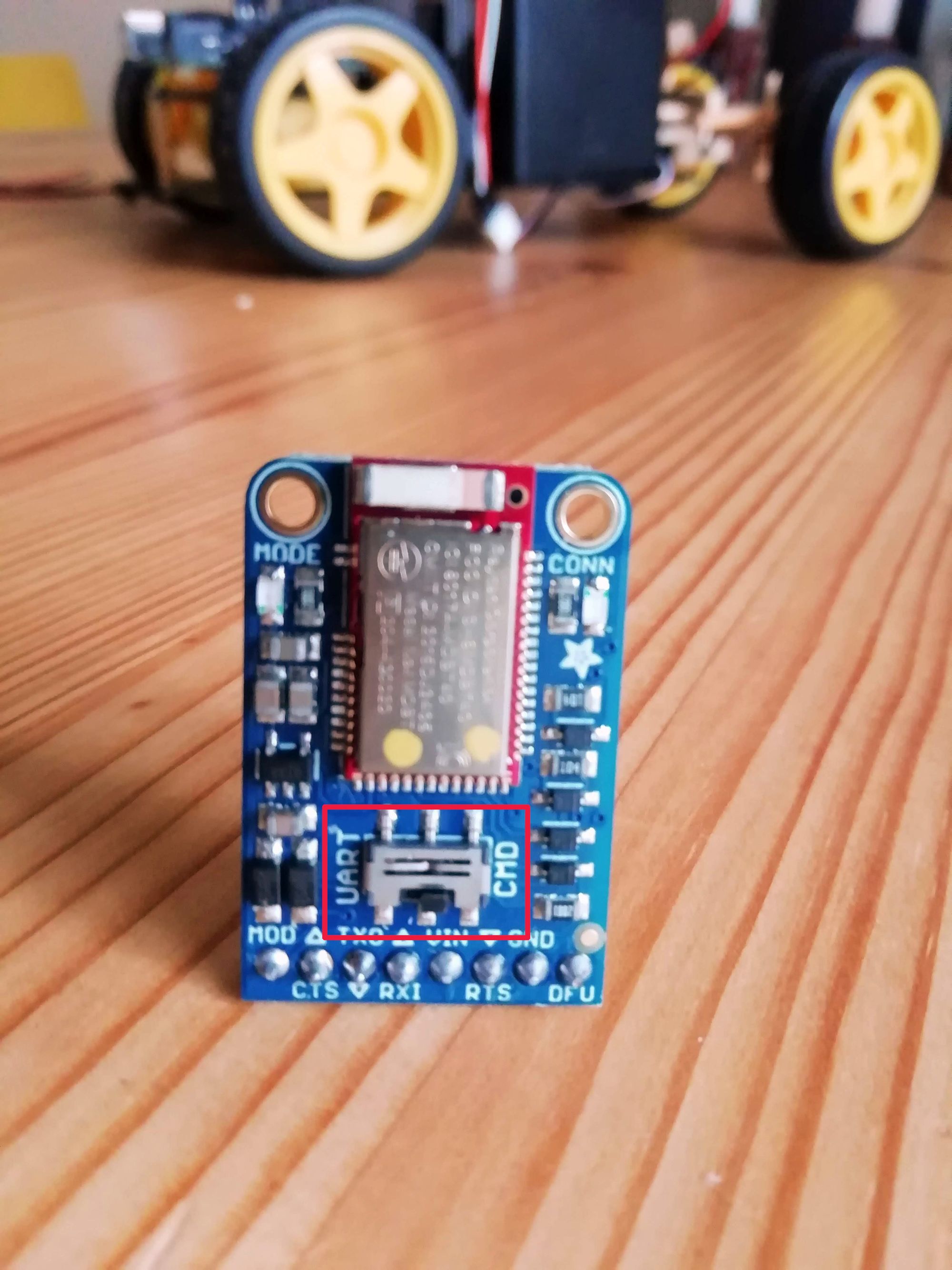
- Hardware Configuration - IMPORTANT!
This simple step is critical and can easily be missed. It could have saved me a bit of time and frustration if I had found it sooner 😅
Set the MODE switch on the module to CMD mode (see image below)
- Upload (and Update)
Once everything has been connected and configured, it's time to upload the code to the Arduino.
It will most likely need updating when you first connect to the module. An update notification will pop up automatically in the app when you connect to it, and it won't take long.
- Control servo motor (for Front Wheel Steering)
I used a servo motor to control the front-wheel steering in this project.
The DC motors can steer the car if you're not using front-wheel steering. See this tutorial as an example.
Connecting the servo motor and adding relevant code changes is relatively straightforward.
Before fastening the servo motor down, double-check everything works and what angles to use. Finding the correct angles for the servo motor to work well with the steering can be a bit of trial and error.
These are the variables I added in BluefruitConfig.h:
// SERVO SETTINGS
#define SERVO_PIN                     6
#define DEFAULT_ANGLE                 90
A servo motor object needs to be added to the main .imo file, just under the Bluefruit object is suitable:
// Create a new servo object:
Servo servoSteering;
In the setup(void) method, we need to initialise it:
// Attach the Servo variable to a pin:
servoSteering.attach(SERVO_PIN);
servoSteering.write(DEFAULT_ANGLE);
Finally, we can add the code to change the angle of the motor, for steering, based on which buttons are pressed in the app, for example:
if (pressed) {
      Serial.println(" pressed");
      if (buttnum == 7) {
        servoSteering.write(45);
      }
      if (buttnum == 8) {
        servoSteering.write(125);
      }
}
Warning! - Be aware that when using the Servo Arduino library, it disables analogWrite() (PWM) functionality on pins 9 and 10, whether or not there is a Servo on those pins. It took me a bit of time to figure this out. ☹️
Running a Servo Motor, DC Motor(s) & Bluetooth Module At The Same Time
Now to the fun part. Make the car drive.
The part below assumes you've two DC motors because the first version of this car had so. You'll not need to add
motor2if you only have one DC motor. This tutorial can be helpful as a extra reference to connect the two motors.
Modify software
We need to add a few bits to our code to get the motor(s) to run. We can use the Cytron Motor Driver library to help us with that.
Similarly, as before, we add some settings for the pins in BluefruitConfig.h:
// MAKER DRIVE MOTOR SETTINGS
#define DRIVE_MOTOR_MODE              PWM_DIR
#define 1A_PIN                        11
#define 1B_PIN                        10
#define 2A_PIN                        3
#define 2B_PIN                        9
We'll also create the motor objects at a similar place where we added the servo object:
// Configure the motor driver.
CytronMD motor1(DRIVE_MOTOR_MODE, 1A_PIN, 1B_PIN);
CytronMD motor2(DRIVE_MOTOR_MODE, 2A_PIN, 2B_PIN);
We then add a few methods to change the speed and directions of the motors:
void robotStop()
{
  motor1.setSpeed(0);
  motor2.setSpeed(0);
}

void robotForward()
{
  motor2.setSpeed(250);
  motor1.setSpeed(250);
}

void robotReverse()
{
  motor1.setSpeed(-50);
  motor2.setSpeed(-50);
}
And finally, we update the loop(void) method where the buttons are pressed with the servo code changes:
if (pressed) {
      Serial.println(" pressed");
      if (buttnum == 7) {
        servoSteering.write(45);
      }
      if (buttnum == 8) {
        servoSteering.write(125);
      }
      if (buttnum == 5) {
        robotForward();
      }
      if (buttnum == 6) {
        robotReverse();
      }
    } else {
      Serial.println(" released");
      if (buttnum == 7 || buttnum == 8) {
        servoSteering.write(DEFAULT_ANGLE);
      }

      if (buttnum == 5 || buttnum == 6) {
        robotStop();
      }
    }
}
Once that's set up, built and uploaded, we're ready to start driving around.
Voila!
It drives and turns 😃
Video of a successful test drive
I'm rather pleased with the outcome of this project and am excited to continue to add extra functionality to it.
Thank you for reading!


Comments ()