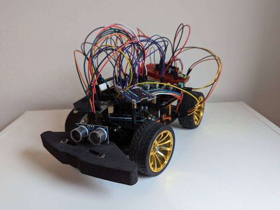
Arduino IoT RC Car: 4 MCUs, Wi-Fi Control and AWS Integration
This is an older post from when this site covered general embedded learning. The site now focuses on modernising classic vehicles.
Introduction
This tutorial combines previous projects into a single IoT RC car with multiple features.
The starting point is the Wi-Fi-Controlled Arduino Car, adding the Feather 32u4 and a distance sensor, a simple "radio" with the pyboard and a piezo buzzer and communicating between the Uno and MKR.
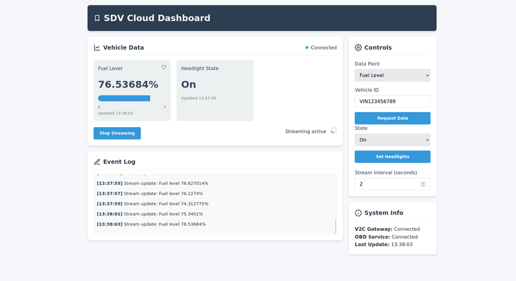
It also includes an OLED display and connects to AWS.
Components Required
- Arduino MKR WiFi 1010
- Arduino Uno R3
- MicroPython pyboard v1.1
- Adafruit Feather 32u4
- Maker Drive H-Bridge Motor Driver
- HC-SR04 Ultrasonic Sonar Distance Sensor
- Step-Up Voltage Regulator (Pololu 5V 3A S13V30F5)
- Piezo Buzzer
- 1.3" OLED Display Module
- Servo motor
- Batteries - 2 x 3.7v & 6v(4 x AA)
- A chassis
- DC motor
- Breadboards
- Jumper wires
Circuit Diagram
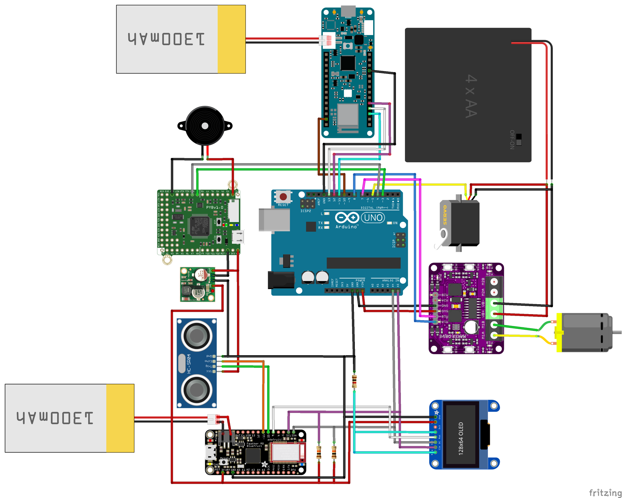
Note: In the image above, what represents the Step-Up Voltage Regulator is an image of a Step-Down Voltage Regulator. But the connections are the same. Same with the OLED display, this is the closest display I could find.
Code
See the GitHub page.
Wiring
| Arduino UNO | py-board | Feather 32u4 | Piezo Buzzer | Step-Up Volt. | HC-SR04 | OLED Display |
|---|---|---|---|---|---|---|
| 4 | X10 | --- | --- | --- | --- | --- |
| 3 | X9 | --- | --- | --- | --- | --- |
| A5 | --- | SCL | --- | --- | --- | SCL w/10k pull-up resistor |
| A4 | --- | SDA | --- | --- | --- | SDA w/10k pull-up resistor |
| --- | Y2 | --- | V+ | --- | --- | --- |
| --- | --- | 10 | --- | --- | Trig | --- |
| --- | --- | 11 | --- | --- | Echo | --- |
| --- | --- | 3V | --- | VIN | --- | Vcc |
| --- | V+ | --- | --- | VOUT | Vcc | --- |
| --- | --- | 9 | --- | --- | --- | RST |
| GND | --- | --- | --- | --- | --- | CS w/1k pull-down resistor |
| GND | --- | --- | --- | --- | --- | DC w/1k pull-down resistor |
| GND | GND | GND | GND | GND | GND | GND |
| Arduino UNO | Arduino MKR | Motor Driver | DC Motor | Servo Motor |
|---|---|---|---|---|
| VIN | --- | 5V | --- | --- |
| 13 | 9 | --- | --- | --- |
| 12 | 10 | --- | --- | --- |
| 11 | 8 | --- | --- | --- |
| 10 | 4 | --- | --- | --- |
| 8 | --- | M1A | V+ | --- |
| 7 | --- | M1B | V- | --- |
| 5 | --- | --- | --- | Signal |
| GND | GND | GND | --- | GND |
Challenges
While building the IoT RC Car, I came across a few challenges. This section outlines the challenges faced during the project and the solutions that led to its completion.
Power Management
In the initial stages, I hoped for a simple setup with a single power source for all components.
However, as the project evolved, it became clear that more than one power source was necessary. I believe the main reasons were the number of devices and varying operating voltages.
Another factor is my understanding of power management, requirements and device compatibility.
I tried many different ways to minimise the need for extra power sources. But I eventually settled on three power sources.
This ensured that each component received the required voltage for optimal performance.
SoftwareSerial Library + Servo Problem
I integrated and tested all microcontrollers together off the car, to begin with and ensure compatibility.
But, once I mounted everything on the car, I encountered unexpected behaviour while attempting to steer. It would jitter and not respond despite working on previous projects.
So what was happening? Were signals getting mixed? Does it need more power for everything? Is the servo broken?
After many reviews, research, and tests, I discovered a common issue. The SoftwareSerial library conflicts with servo operations.
Everything changed thanks to the Arduino forum, particularly from Robin2, who had developed an improved version.
This change resolved the conflict, allowing the car to steer and function as intended.
Critical Motor Driver Selection
The next challenge quickly surfaced when attempting to steer and drive. I could steer and drive forwards and backwards, but not simultaneously.
It looked like the car needed more power. Or it was too heavy.
But then, one day, a potential solution cropped up as I scrolled through Reddit.
I learned that L298N and other motor drivers using Darlington transistors were known for their high voltage drops and unsuitable for RC projects. This aligned with the car's performance limitations.
Following this insight, I replaced the L293D driver with the Maker Drive, resulting in a remarkable transformation. The new motor driver delivered enhanced power, enabling the car to steer and drive at the same time.
A Fundamental Oversight: The Ground
I can't count the times I finally thought I had figured something out, only for it not to work, and I'm puzzled about why.
Then, I realized I had overlooked a fundamental step: connecting the ground. Voila! Everything is working as I had hoped.
It is a simple thing to forget, but it can make you question your whole existence.
Understanding Pull-Up/Down Resistors
The final challenge involved integrating a display supporting SPI communication by default while I needed to use I2C.
This meant some connections were not utilised and required pull-up/down resistors.
Despite initial unfamiliarity with these components, it was a valuable learning experience.
I recommend SparkFun's article for those interested in delving deeper into pull-up resistors.
In conclusion, building the IoT RC Car was not without its obstacles. Yet, each challenge served as an opportunity for growth and learning.
Thank you for reading!

Comments ()