DC & Servo Motor Control in C++ with Raspberry Pi
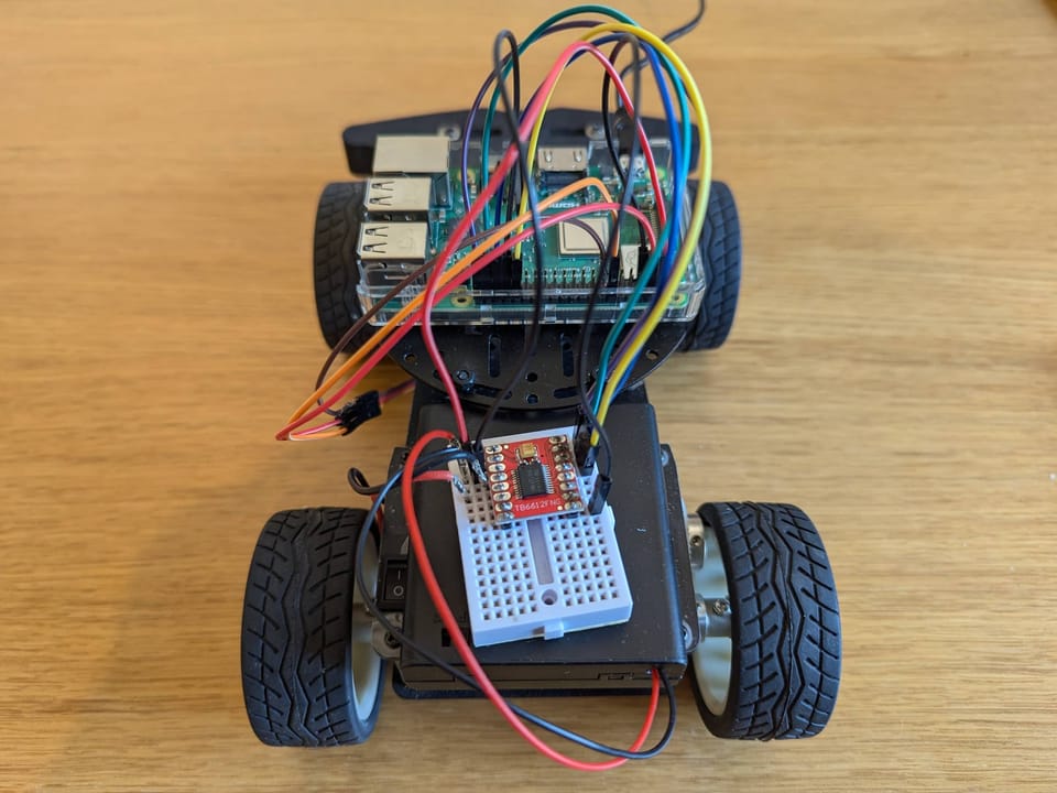
Below, we'll demonstrate how to control a DC motor and servo motor (MG996R) using a Raspberry Pi and a TB6612FNG motor driver.
The motor driver can control two DC motors simultaneously, and you can find an Arduino example here. I will only use one DC motor in this guide.
Required Components
- Raspberry Pi (I used 3 B+)
- TB6612FNG motor driver
- 4 x AA Battery (6V)
- DC motor
- Servo motor (I had the MG996R)
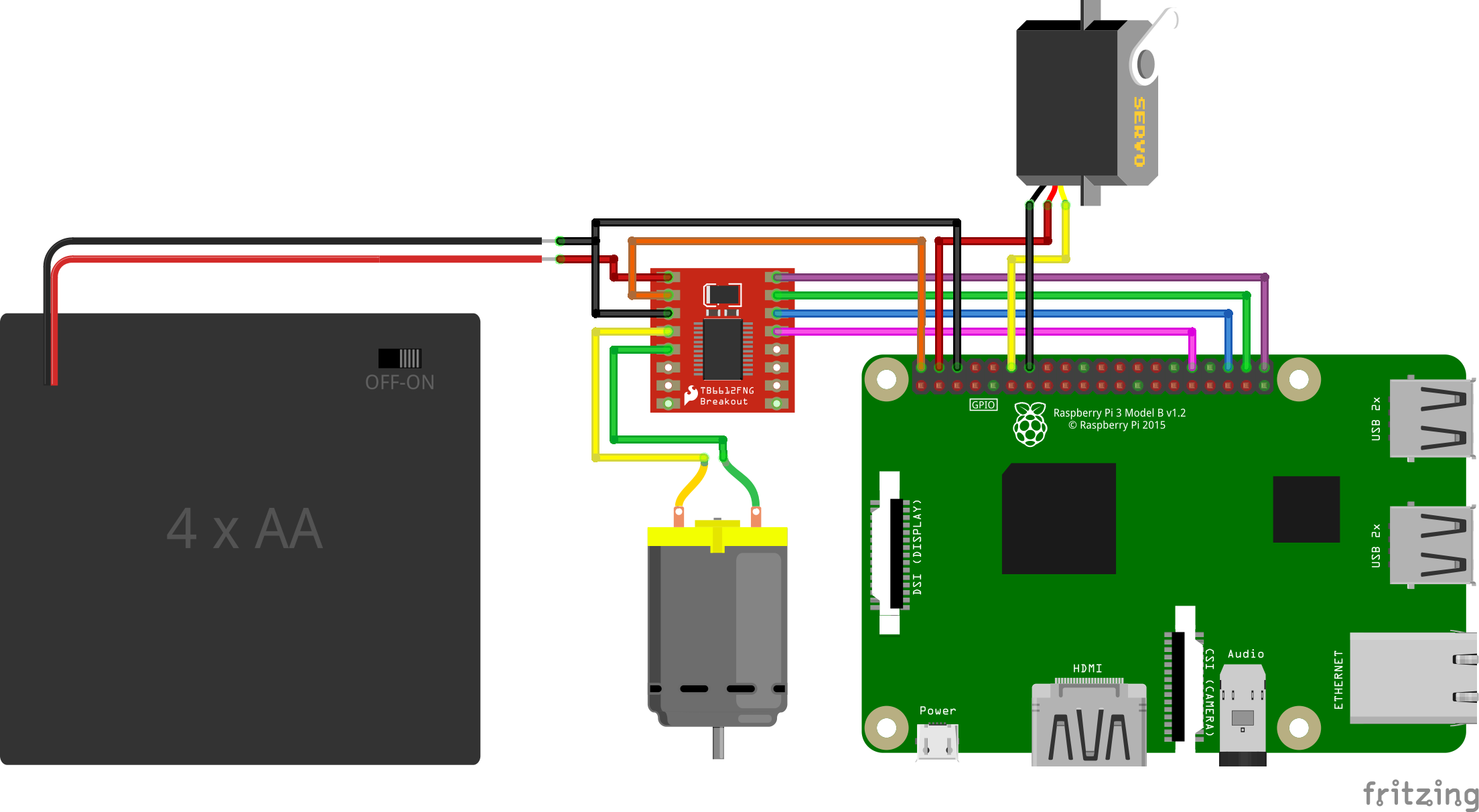
Circuit Diagram
Code (MotorDriver)
Click to see some code.
MotorDriver.h
#ifndef MOTOR_DRIVER_H
#define MOTOR_DRIVER_H

class MotorDriver {
    private:
        int In1, In2, PWM, Offset,Standby;
        void fwd(int speed);
    	void rev(int speed);
        bool DEBUG = false;
    public:
        MotorDriver(int In1pin, int In2pin, int PWMpin, int STBYpin);
        void drive(int speed);
        void brake();
        void standby();
        void setDebug(bool);
};

#endif /* MOTOR_DRIVER_H */
MotorDriver.cpp
#include <stdio.h>
#include <softPwm.h>
#include <wiringPi.h>
#include "MotorDriver.h"

MotorDriver::MotorDriver(int In1pin, int In2pin, int PWMpin, int STBYpin)
{
    In1 = In1pin;
    In2 = In2pin;
    PWM = PWMpin;
    Standby = STBYpin;

    pinMode(In1, OUTPUT);
    pinMode(In2, OUTPUT);
    softPwmCreate(PWM, -255, 255);
    pinMode(Standby, OUTPUT);
}

void MotorDriver::fwd(int speed)
{
    digitalWrite(In1, HIGH);
    digitalWrite(In2, LOW);
    softPwmWrite(PWM, speed);
}

void MotorDriver::rev(int speed)
{
    digitalWrite(In1, LOW);
    digitalWrite(In2, HIGH);
    softPwmWrite(PWM, speed);
}

void MotorDriver::drive(int speed)
{
    digitalWrite(Standby, HIGH);
    if (speed >= 0)
        fwd(speed);
    else
        rev(-speed);
}

void MotorDriver::brake()
{
    digitalWrite(In1, HIGH);
    digitalWrite(In2, HIGH);
    softPwmWrite(PWM, 0);
}

void MotorDriver::standby()
{
    digitalWrite(Standby, LOW);
}
Code (main)
Click to see some code.
main.cpp
#include <wiringPi.h>
#include <softPwm.h>
#include "MotorDriver.h"

using namespace std;

#define SERVO 1

#define STBY 26
#define AIN1 27
#define AIN2 28
#define PWMA 29

int main() {
    wiringPiSetup();

    // DC motor
    MotorDriver motor(AIN1, AIN2, PWMA, STBY);

    motor.drive(255);
    delay(1000);
    motor.brake();
    motor.drive(-255);
    delay(1000);
    motor.brake();

    // Servo motor
    softPwmCreate(SERVO, 0, 200);

    // 15 (1500us pulse) is middle position, 10 (1000us pulse) is 0 degrees, 20 (2000us pulse) is 180 degrees
    softPwmWrite(SERVO, 15); // Move to 90 degrees
    delay(1000);
    softPwmWrite(SERVO, 12); // Move to 0 degrees
    delay(1000);
    softPwmWrite(SERVO, 18); // Move to 180 degrees
    delay(1000);
    softPwmWrite(SERVO, 15); // Move back to 90 degrees
    delay(1000);

    return 0;
}
Wiring
The computer powers the Raspberry Pi via USB. The Raspberry Pi then powers the motor driver, and I use a 4 x AA battery (6V) to power the DC motor through the motor driver (VM). Check the specs for your motors and what power they need.
| Raspberry Pi | TB6612FNG motor driver | DC motor | Servo motor | 6v Battery |
|---|---|---|---|---|
| - | VM | - | - | V+ |
| 5V | VCC | - | - | - |
| 32 (GPIO.26) | STBY | - | - | - |
| 36 (GPIO.27) | AIN1 | - | - | - |
| 38 (GPIO.28) | AIN2 | - | - | - |
| 40 (GPIO.29) | PWMA | - | - | - |
| - | A01 | V+ | - | - |
| - | A01 | V- | - | - |
| 12 (GPIO.1) | - | - | Orange | - |
| 5V | - | - | Red | - |
| GND | GND | V- | Brown | V- |
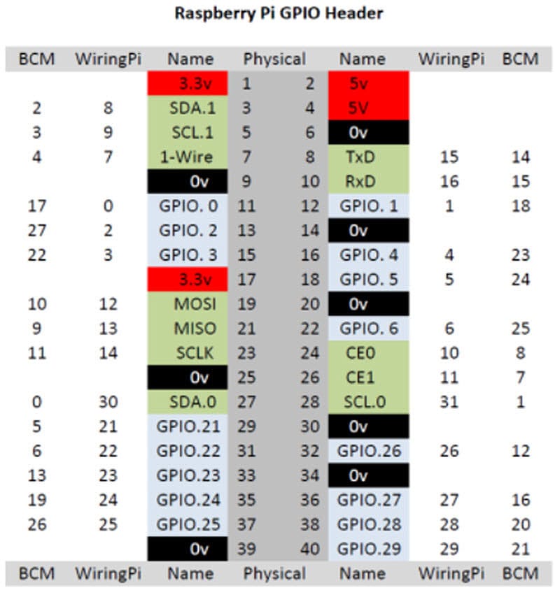
Note that the pin numbering in wiringPi is not straightforward. Use the image below to link the physical pins on the Raspberry Pi board to the WiringPi pin numbers.
Results
Here, you can see a video of the motors running with the above setup.
Video of a Raspberry Pi running a DC motor and a servo motor.
Thank you for reading!
Hopefully, this has helped you in some way with your project.