Microcontroller Peripherals: GPIO, Timers, ADC, UART & More

Introduction
Microcontrollers (MCUs) are the brains behind modern electronics, controlling everything from your smart thermostat to complex industrial machinery. What makes them so powerful isn’t just their central processor—it's their peripherals built right into them that enable them to interact with the outside world. Without peripherals, a microcontroller is just a digital brain that can't sense or control anything in the real world.
In this article, we'll walk through the most common microcontroller peripherals, how they work, and how to use them. We'll explain them in simple terms, relating them to real-world applications like reading sensors, blinking LEDs, and communicating with other devices.
What Are Peripherals?
Peripherals are specialised hardware components inside the microcontroller that support interaction with external systems, sensors, and devices. Think of them as "built-in hardware tools" that you configure and control using software.
Think of peripherals as built-in assistants—each one specialises in a different task to help your microcontroller do its job more efficiently.
They handle:
- Input/Output (e.g., reading a button press, turning on an LED)
- Communication (e.g., sending data to a GPS module or another microcontroller)
- Timing (e.g., blinking LEDs at regular intervals, controlling motor speed)
- Signal Conversion (e.g., reading analogue voltages from a temperature sensor)
- Control Logic (e.g., responding to external events)
They offload specific tasks from the main processor, allowing the CPU to focus on more complex computations rather than constantly managing basic I/O or communication. For example, instead of the CPU constantly checking if a button is pressed, a GPIO peripheral can be configured to generate an "interrupt" (an alarm) only when the button's state changes.
Common Peripherals Explained
To configure and control these peripherals, you typically interact with special memory locations called registers. By writing specific values to these registers, you tell the peripheral how to behave. Thankfully, many microcontroller development kits provide Hardware Abstraction Layers (HALs) or libraries that simplify this process, allowing you to use more intuitive function calls instead of direct register manipulation.
1. GPIO – General Purpose Input/Output
- What it is: GPIO pins are the simplest and most fundamental way for a microcontroller to interact with the outside world. They are simple pins that you can configure as either an input (to read signals) or an output (to send signals). GPIOs handle only digital signals—so it's either a 1 (high) or 0 (low).
- How it works:
- Input: When configured as an input, the GPIO pin can detect if an external voltage is high (e.g., 3.3V or 5V, representing a digital '1') or low (e.g., 0V, representing a digital '0'). This is perfect for reading the state of buttons or switches. To ensure stable readings when a button isn't pressed, you often use "pull-up" or "pull-down" resistors, which prevent the input from "floating" to an unknown state.
- Output: When configured as an output, the microcontroller can set the pin's voltage to high or low, effectively turning an external component on or off.
- Used for: Buttons, LEDs, switches, relays, and simple digital sensors.
Example in C (STM32 HAL):
// Turn on LED connected to pin A5
HAL_GPIO_WritePin(GPIOA, GPIO_PIN_5, GPIO_PIN_SET);
// Read state of button connected to pin B0
HAL_GPIO_ReadPin(GPIOB, GPIO_PIN_0);
2. Timers
- What it is: Timers are specialised counters that can generate precise time delays, create periodic interruptions, or produce Pulse Width Modulation (PWM) signals.
- How it works: Timers count clock cycles. When they reach a specific count, they can trigger an event.
- Time Delays & Scheduling: By setting a timer to count for a specific duration, you can create precise delays for operations or schedule tasks to run at regular intervals (e.g., checking a sensor every 100 milliseconds). These can trigger "timer interrupts," which are signals to the CPU to execute a specific piece of code when the timer event occurs.
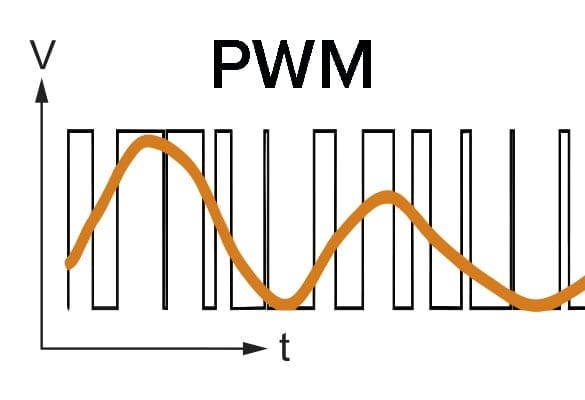
- PWM (Pulse Width Modulation): This is a powerful technique in which the timer generates a square wave signal with a varying "on" time (pulse width) relative to the total period. By adjusting the pulse width, you can effectively control the average power delivered to a device, allowing for smooth dimming of LEDs or precise control of DC motor speed. It sort of creates the illusion that something is happening smoothly or gradually, when in fact it is just turning things on and off for varying periods.
- Used for: Motor control, signal generation, creating delays, real-time clock functions, scheduling events.
Example:
- A timer can be configured to generate a 1 kHz PWM signal, allowing for the smooth dimming of an LED or control of a small fan's speed.
- The '1 kHz' in a 1 kHz PWM signal refers to the frequency at which the entire cycle (on time + off time) repeats 1000 times per second. This frequency is chosen based on the application; for LEDs, higher frequencies prevent flickering, while for motors, it might relate to how smoothly they operate.
3. ADC – Analogue-to-Digital Converter
- What it is: The ADC converts analogue signals (like varying voltages from a sensor) into digital numbers that the microcontroller can understand and process.
- How it works: Real-world signals (temperature, light, sound, pressure) are often analogue, meaning their values can vary continuously. The ADC takes an analogue voltage and quantifies it into a discrete digital value.
- Resolution and Reference Voltage: This defines how precisely the ADC can measure the analogue signal. A 12-bit ADC, for example, outputs a digital value between 0 and 4095 (2^12 − 1). The ADC also requires a reference voltage (e.g., 3.3 V or 5 V). This reference voltage defines the upper limit of the analogue voltage range that the ADC can measure. For instance, if the reference is 3.3V, a digital value of 0 corresponds to 0V, and 4095 corresponds to 3.3V at the input pin. Your code then uses this relationship to convert the digital number back into a meaningful physical measurement. Therefore, if you receive a value of 2035, the code must perform calculations to obtain the correct value of 20˚C.
- Used for: Reading temperature sensors (like thermistors), light sensors (photoresistors), potentiometers, microphones, and other analogue input devices.
Typical resolution: 10-bit or 12-bit (values from 0–1023 or 0–4095)
4. UART – Universal Asynchronous Receiver/Transmitter
- What it is: UART is one of the simplest and most common serial communication protocols. "Serial" means data is sent one bit at a time over a single line, unlike "parallel" communication, which uses multiple lines simultaneously. UART is "asynchronous" because it doesn't require a shared clock signal between devices; instead, it relies on agreed-upon communication settings (like baud rate).
- How it works: UART typically uses two wires: one for transmitting data (TX) and one for receiving data (RX). Data is sent as a stream of bits, framed with start and stop bits to synchronise the receiver.
- Used for: Debugging (sending messages to a computer terminal), communicating with other devices like GPS modules, Wi-Fi modules, Bluetooth modules, or even other microcontrollers.
Example:
// Transmit "Hello World!" over to UART2.
// The number of bytes (characters) to transmit is 12.
// 100 millisecond timeout to indicating how long the function should wait for the transmission to complete before giving up.
HAL_UART_Transmit(&huart2, "Hello World!", 12, 100);
5. I2C (Inter-Integrated Circuit) & SPI (Serial Peripheral Interface)
These are two other widely used serial communication protocols, offering different advantages for specific applications.
- I2C (Inter-Integrated Circuit):
- What it is: A two-wire serial protocol designed for short-distance, low-speed communication between a "controller" device (usually the microcontroller) and multiple "target" devices.
- How it works: It uses just two wires: SDA (Serial Data Line) and SCL (Serial Clock Line). Multiple target devices can share the same two wires, each identified by a unique 7-bit address. The controller initiates communication with a specific target by sending its address.
- Used for: Communicating with sensors (e.g., temperature, accelerometer), EEPROMs (memory chips), Real-Time Clocks (RTCs), and small OLED displays.
- SPI (Serial Peripheral Interface):
- What it is: A faster, full-duplex (can send and receive simultaneously) serial communication protocol often used for higher-speed data transfer.
- How it works: SPI typically uses four wires: SCLK (Serial Clock), MOSI (Master Out Slave In), MISO (Master In Slave Out), and SS/CS (Slave Select/Chip Select). The controller ("master") generates the clock signal, and each target ("slave") device has its own dedicated Chip Select line, allowing the controller to select which target it wants to communicate with.
- Used for: Connecting to flash memory chips, SD card modules, LCD displays, and some high-speed sensors.
| Protocol | Wires | Typical Speed | Key Feature / Use Case |
|---|---|---|---|
| UART | 2 | ~1 Mbps | Debugging, GPS modules, simple point-to-point communication. |
| I2C | 2 | ~400 kHz | Multiple devices on shared bus, sensors, RTCs, EEPROMs. |
| SPI | 4 | 10+ Mbps | Faster, full-duplex, displays, flash memory, cards. |
6. DAC – Digital-to-Analogue Converter
- What it is: The DAC performs the opposite function of an ADC; it converts digital numbers from the microcontroller into an analogue voltage.
- How it works: The microcontroller outputs a digital value, and the DAC generates a corresponding analogue voltage.
- Used for: Generating audio waveforms, creating variable voltage references, or providing analogue control signals to external circuits (e.g., motor speed control where PWM might not be suitable).
Example Use Cases
Let's see how these "hardware tools" work together in common embedded projects:
Use Case 1: Button-press turns on an LED
- GPIO Input for the button: The microcontroller reads the digital state of the button (pressed or not pressed).
- GPIO Output for the LED: Based on the button's state, the microcontroller sets the LED pin to high or low, turning the LED on or off.
Use Case 2: Read temperature sensor (analogue) and print over UART
- ADC for the sensor: The ADC converts the analogue voltage from the temperature sensor into a digital value.
- UART for communication: The microcontroller then sends the digital temperature value as text to a computer or another display device for debugging or monitoring purposes.
Use Case 3: Dim LED with PWM
- Timer in PWM mode: A timer is configured to generate a PWM signal.
- GPIO Output to LED: This PWM signal is sent to an LED through a GPIO pin. By varying the "on" time of the pulse, the LED's brightness can be smoothly controlled from fully off to fully on.
Use Case 4: Logging Temperature Data to an SD Card
- ADC for temperature sensor: Converts the analogue temperature reading into a digital value.
- SPI for SD card communication: The microcontroller uses the SPI peripheral to write the digital temperature data to an SD card for long-term storage.
- UART for debugging: While the system is running, the microcontroller can also send the temperature data to a computer via UART, allowing a developer to monitor the process in real-time.
Conclusion
Microcontroller peripherals are the bridge between your digital code and the analogue real world. By understanding how to configure and use these essential "built-in hardware tools"—GPIO, Timers, ADCs, UART, I2C, and SPI—you unlock the full potential of your microcontroller, enabling it to sense, communicate, and control the environment around it. Mastering these peripherals is a crucial step in becoming proficient in embedded systems development.