From Idea to Reality: Building a Car Battery Monitor PoC with AI Help
Introduction:
As I work on disassembling my 1972 MGB GT, Benni, for restoration, I always look for ways to use technology to improve things. One of the first ideas that came to mind was a battery-monitoring device. Because Benni's battery isn't easily accessible – it's located under the rear seats – it felt like a perfect fit for a first project to monitor the battery's health more conveniently.
However, my electronics knowledge is somewhat basic, especially when it comes to picking the right components and making sure they work well together. I often didn't know which parts to choose, what features to look for, or how they all connected to form a working system.
So, I decided to use AI as my consultant and mentor on these matters, guiding me through the whole process, from the initial design idea to troubleshooting.
My aim is to design and build a reliable battery voltage monitor that shows data on a smartphone app using Bluetooth Low Energy (BLE).
From Idea to Initial Design & Component Selection (AI as a Design Consultant)
It all began with a simple question: What do I need to monitor a battery's voltage? And if I'm using a microcontroller, how can it read a 12-volt battery when it typically operates at 3.3 volts?
So, I turned to AI to help me explore this idea and get a basic grasp of the electronic principles involved.
AI quickly suggested the main parts I'd need, including a microcontroller and a way to measure voltage. It reminded me of the idea of a "voltage divider," a concept I had completely forgotten about.
Cars also have fluctuating electrical systems due to temperature changes, different loads, or the battery's charge level. This made it clear that I'd need a robust system. It had to handle the car's changing 12V supply while providing a stable, low voltage for my microcontroller.
I chose the ESP32 as my microcontroller. I already owned one, and its built-in Bluetooth capabilities were perfect for sending data to a smartphone app, which was a core part of my plan.
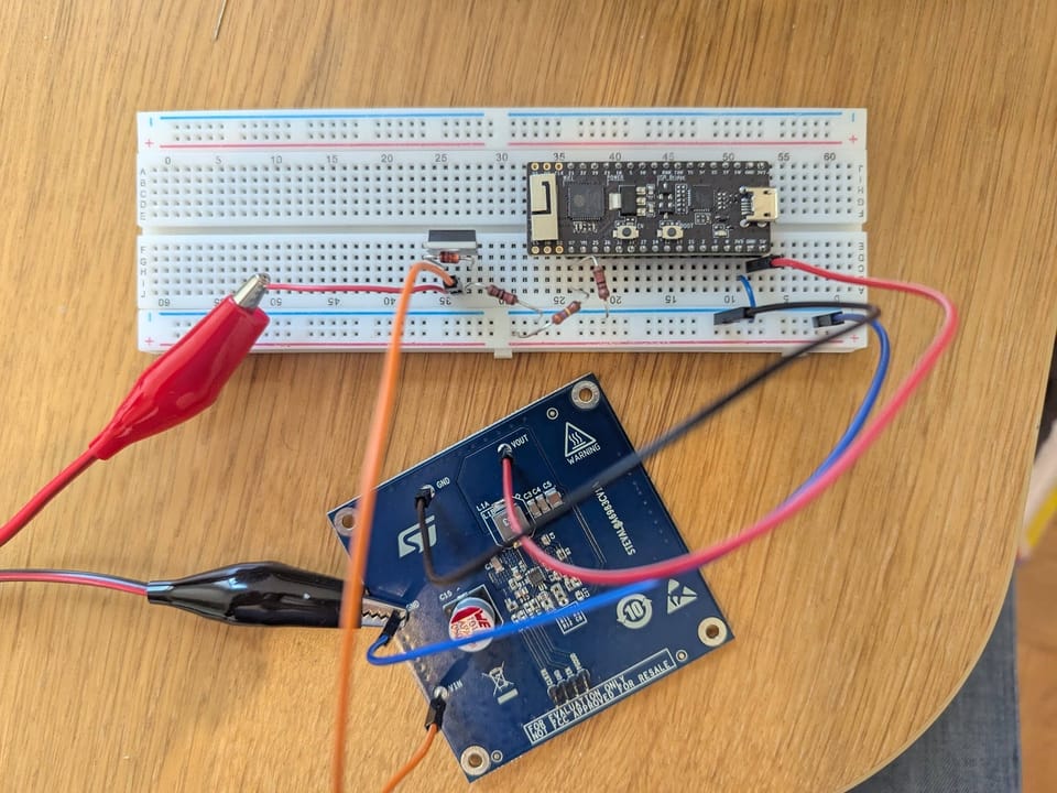
After a quick chat to understand the basics and how they might fit together, it was time to start building. I began with a 9V battery for a quick "proof of concept" and used parts from an old Arduino Starter Kit. Then, I asked the AI for help in setting up a basic system.
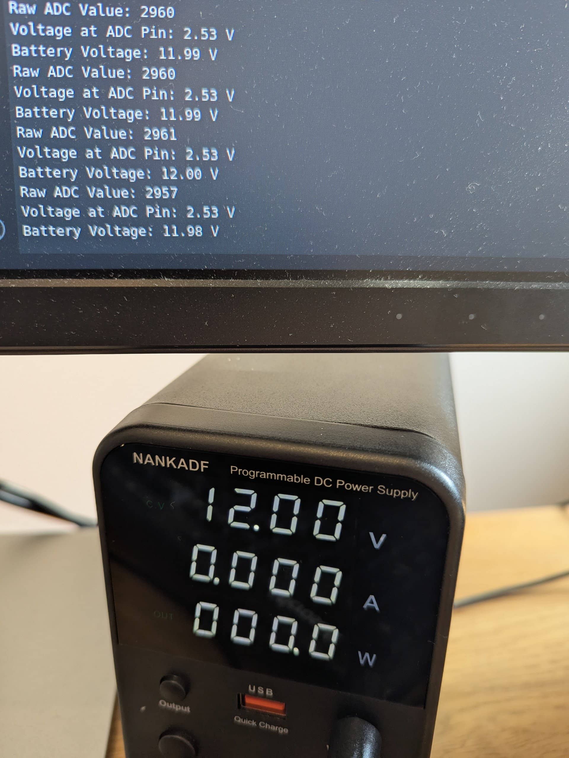
AI provided me with the necessary components, instructions on how to connect them, and a basic Arduino code to upload and test. And it worked like a charm!
Well, sort of. The readings weren't exactly right, but that didn't matter. I was getting some values, and that was a huge win. My next step was to make it more suitable for a 12V system, so I bought an adjustable power supply and upgraded some components.
To measure the battery's voltage, a voltage divider was essential. This circuit steps down the car's 12V (which can go up to 14.5V when charging and even higher during quick voltage spikes called "transients") to a safe level for the ESP32's Analogue-to-Digital Converter (ADC), typically 0-3.3V.
Working back and forth with AI, I selected a voltage divider with R1 = 37.4 kΩ and R2 = 10 kΩ. This setup ensures that even at a maximum battery voltage of 15V, the voltage going into the ADC will be approximately 3.165V, falling comfortably within the ESP32's safe operating range.
I also wanted to power the microcontroller directly from the car's 12V battery. To do this, I needed a buck DC/DC converter, which efficiently steps down a higher voltage to a lower one. I first looked at the LM5013 from Texas Instruments. However, after discussing it with AI, I wasn't convinced it was the best fit for a car's electrical system, so I asked for advice on what features to look for in a more robust buck converter.

AI's advice on automotive-grade components and the complexities of power supply design led me to consider a pre-built solution. After some research, I found the STEVAL-A6983CV1 evaluation board. This board, which features the A6983 buck converter, offers significant benefits: it's designed specifically for automotive use, can handle input voltages up to 38V (and even tolerate short "load dump" spikes up to 40V), and importantly, the STEVAL-A6983CV1 provides a fixed and regulated 5V output.
This fixed output simplifies the power supply design by eliminating the need for external resistors to set the voltage. Choosing this evaluation board significantly sped up my initial development by giving me a ready-made and optimised power supply section.
Power, Protection, and Data Acquisition (AI as a Technical Advisor)
A key idea from the start of my design was that safety is absolutely critical, especially in the automotive environment of a classic car. Cars present unique and tough challenges for electronic circuits due to a mix of fluctuating electricity, physical vibrations, and extreme temperatures. Because of this, any electronic circuit installed in a vehicle must have strong safety and protection features built in from the very beginning.
Once I had decided on the main components, the next step was to incorporate these safety features into the design. Getting help from AI was a huge boost in guiding me through the details of protecting the power input and getting reliable data.
Safety First - Power Input & Protection:
A car's electrical system is unpredictable, so connected electronics need strong protection.
- Fuses: AI emphasised how vital fuses are as the first line of defence against too much current. Placing the fuse as close to the car battery as possible protects the entire circuit and the car's wiring from damage. While I've chosen the fuse holder and fuse, I still need to add them to my setup.
- Reverse Polarity Protection: Protecting the circuit from accidentally connecting the battery the wrong way was also a top priority. AI suggested a solution using a P-Channel MOSFET.
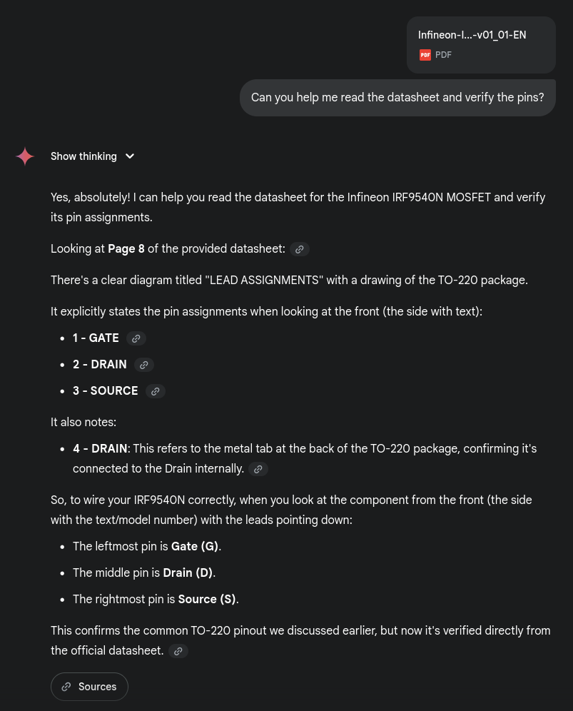
- I selected the Infineon IRF9540NPBF MOSFET after asking AI what characteristics to look for. This P-Channel MOSFET can handle 100V between its Drain and Source and a continuous current of 23A. This makes it very suitable for a 12V car system.
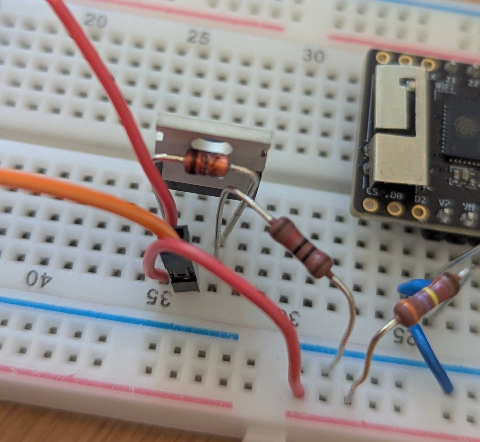
- AI even helped me verify how to connect the MOSFET pins and pointed to where this information was in the datasheet so I could double-check myself, which was quite cool. (See image below)
- I included a 10kΩ pull-down resistor, connecting it from the MOSFET's Gate pin to the circuit's ground. AI explained that this resistor ensures the MOSFET stays turned off when there is no power input or if the battery is connected in reverse by pulling the Gate pin down to ground.
- For extra protection of the MOSFET's control pin (Gate), AI advised using an 18V Zener diode (1N4746A). In simple terms, this Zener diode limits the voltage across the Gate and Source pins to 18V, preventing it from exceeding this level and potentially damaging the MOSFET's delicate internal structure. This entire reverse polarity protection circuit has been successfully built on the breadboard.
- Over-Voltage Protection (TVS Diode): AI pointed out that while Zener diodes protect individual components, a Transient Voltage Suppressor (TVS) diode is crucial for overall system protection. It guards against high-energy voltage spikes, like those that can occur when the alternator suddenly stops charging a battery ("load dump") in a car. Being able to ask AI what to consider when choosing such a specialised part was incredibly helpful. Unfortunately, I've not yet added the TVS diode to my setup because I received the wrong type.
AI even helped me verify how to connect the MOSFET pins and pointed to where this information was in the datasheet so I could double-check myself, which was quite cool.
Clean Data - Voltage Divider & Filtering:
The voltage divider (R1=37.4kΩ, R2=10kΩ) is responsible for reducing the battery's voltage to a level that the ESP32's ADC can read. To make sure these readings are accurate and stable, especially in a noisy car, AI recommended a couple of key additions:
- A 0.1µF ceramic capacitor was placed next to R2 (the 10kΩ resistor) in the voltage divider. Its job is to filter out high-frequency electrical noise and smooth out any small voltage changes, giving a cleaner signal to the ADC. This filter capacitor has been successfully added.
- ADC Input Zener Diode: AI also suggested including a 3.6V Zener diode specifically to protect the ESP32's ADC input pin. This would act as a final safeguard against any remaining voltage spikes that might get past the other protection layers. My attempt to add this Zener diode didn't work as planned; it caused a big voltage drop in the reading from 12V down to 7.3V. AI provided some ideas about potential issues, such as incorrect Zener polarity or the absence or incorrect value of a current-limiting resistor in series with the Zener. However, even after trying those solutions, the problem persists, and I have yet to figure this one out.
Next Steps and Future Enhancements
With the basic parts now taking shape on the breadboard, the next steps involve making the setup truly robust, ensuring all necessary protections are in place, and preparing it for actual use in the car.
Immediate Next Steps:
- Fuse Integration: The fuse and fuse holder are crucial for safety and will be the very next components to be installed at the main power input.
- TVS Diode Integration: Finding and installing the correct TVS diode is essential. This will provide powerful, system-wide over-voltage protection against the harsh electrical spikes common in cars.
- ADC Input Zener Diode: I will go back to trying to integrate the 3.6V Zener diode for the ESP32's ADC input protection, hopefully solving the current mystery.
- Transition from Evaluation Board: While the STEVAL-A6983CV1 evaluation board is great for testing, it's not ideal for permanent in-car use due to its size and exposed components. The next step will be to design and build a custom power supply section based on the A6983 buck converter IC (or a similar robust alternative) onto a more compact and durable perfboard or custom PCB. This will involve selecting individual components (input/output capacitors, inductors, diodes) as per the A6983 datasheet and layout recommendations. I'll probably get AI to help me with this.
- Transition to Permanent Board: Once all components are successfully added and thoroughly tested on the breadboard, the entire circuit will be moved to a more permanent perfboard or, ideally, a custom Printed Circuit Board (PCB). This will make it much more reliable and durable for use in the car.
Software Development: I decided to use a smartphone app to show the data, which simplifies the hardware and shifts focus to the software. I have a basic solution working, but the next step is to keep improving it. This includes:
- Improving the ESP32 firmware to set up Bluetooth Low Energy (BLE), create a custom service and characteristic (like a data channel), read the calibrated battery voltage, and let other devices find it.
- Continuing to develop the smartphone app so it can scan for the ESP32's BLE signal, connect to the device, read the voltage data, and display it in an easy-to-understand way.
In-Car Deployment: The final stage will involve carefully installing the finished system in my classic car. This includes:
- Securely mounting the enclosure (the case for the electronics) inside the vehicle.
- Making strong and properly fused connections to the car's electrical system. This means connecting the voltage divider directly to the battery-positive terminal and ensuring the buck converter receives power from a suitable, always-on source in the car's fuse box.
- Thoroughly testing the system under various car conditions (engine off, during starting, and while running) to check the readings on the smartphone app and look for any electrical interference.
Potential Future Enhancements: My current project focuses on just monitoring voltage, but the design's flexibility allows for exciting future upgrades:
- Current Monitoring: Adding a current shunt (a very low-resistance resistor) and a current sense amplifier would allow real-time measurement of current flowing to and from the battery. This would provide deeper insights into how quickly the battery is discharging or charging, as well as overall power usage.
- Advanced Battery Health: By looking at both voltage and current data, I could use calculations to estimate the battery's State of Charge (SOC) more accurately and even track its internal resistance over time.
- Alerts and Notifications: Adding features to send alerts to the smartphone app if the battery voltage drops too low or if there's an unusual power draw.
Conclusion:
Using AI to bring this idea to life has been amazing. When you start with a project like this, you often don't know how or where to begin, and I believe this is where AI can be extremely helpful. It can provide a solid starting point, which you can then test, question, or adjust to fit your specific needs and wants.
For this project, AI has helped to simplify and make electronic design easier to understand. From suggesting the first components and guiding complex wiring to helping me solve problems, AI has been an essential partner throughout. Being able to ask detailed questions and receive clear, helpful answers has not only made the development faster but has also greatly helped me learn a lot and improve my own understanding of how these systems work.
As I move closer to finishing and installing this battery voltage monitor, combining my passion for classic cars with AI-assisted engineering feels like a compelling example of what's possible in today's DIY electronics.